Wednesday, May 16, 2018

Five Critical Factors in Industrial Control System Integration

Ali Awais Amin


Control system integration is fundamental to industrial automation. Automation professionals with even a rudimentary knowledge of system integration realize and understand that isolation is coming to an end. In fact, control system integrators provide maximum value to the client by designing the system called for by the project parameters rather than having to tailor a particular proprietary system according to the specific requirements.
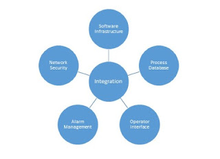
There are five factors involved in integrating different control systems:
  1. Software infrastructure
  2. Process databases  
  3. Operator interface
  4. Alarm management
  5. Network security.
Each has a vital role to play. Here is an in-depth look at each one:
1. Software infrastructure: A modern automation system needs more than just configuration and monitoring functions. Applications also must be integrated, which is why software infrastructure is important for system integration. In an open software architecture employing a client-server scheme, the client application displays data from a server application.
Developed by the OPC Foundation, the OLE for process control-unified architecture (OPC-UA) technology is designed to provide simpler browsing and real-time and historical data exchange. OPC-UA provides integrators more flexibility to integrate different systems in a desired configuration instead of being locked into a specific setup by proprietary technology. The standard's focus is interoperability and is designed to connect many devices to create a bridge from legacy products to new devices. 

2. Process database: Database components primarily include three main components: one or more tables for the data, a query language (e.g., SQL), and forms for displaying or entering data. Additional components include customized page views of data and reporting tools. Moreover, a relational database is a collection of data items. These data items are organized as a set of formally described tables from which data can be accessed in many ways without the need to reorganize the database tables.
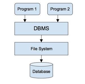
A database management system (DBMS) collects interrelated files and programs, which allow users to access and modify files. This is an efficient way to modify, store, and retrieve information. A query language such as SQL is used to interact with DBMS. 

3. Human-machine interface: The human-machine interface (HMI) allows operators to monitor the state of a control process and issue commands to change the control objective. In emergency situations, it can also be used to manually override automatic controls. The primary aspects of HMI configuration are graphics, historical trend, alarms, reports, and scripts. These capabilities may either be merged into a single software application or made available as individual components in a suite. 

4. Alarm management: Alarms mark the boundary between normal and abnormal conditions in the process and serve as the primary means of alerting operators of abnormal situations in their facilities. Plant operation requires alarms to be prioritized, relevant, and timely to be effective. Alarm management is critical when integrating different control systems and so alarm systems need to be designed to help identify critical issues. 

5. Network security: Integrated control and safety systems (ICSS) operate within a complex environment with organizations increasingly sharing information between business systems and industrial systems. In addition to this, industrial systems, which include process control systems, safety systems, and programmable logic controllers (PLCs) have relied on commercial, off-the-shelf (COTS) technologies such as Ethernet, TCP/IP and Microsoft Windows for critical and noncritical functions. However, the isolation from the outside world is significantly less. In fact, in an event of security breach, the potential loss of life or production, environmental damage, and compromise to operational safety are far more serious consequences than loss of trade secrets. 

These may have ramifications beyond the targeted organization and may also damage the infrastructure of the host region or nation. 

A detailed cybersecurity analysis and cyber risk assessment are required. They should include detailed specifications, policies and procedures for OS patch management, antivirus implementation, and backup and restore procedures. 

Automation does not merely comprise of equipment control. It includes higher levels of control that manage personnel, materials, and equipment across all factory production areas. This usually is accomplished using the documented procedures and software collectively known as the manufacturing execution system (MES) layer. MES is a control system for managing and monitoring important tasks in a plant. It supports the planning and control all the way to finished product, which brings transparency to the highly complex production tasks. 

Four categories of enterprise and control systems are defined by the ISA-95 depending on their roles. These categories are organized in a hierarchical model in which activities associated to each category are specified. The image below illustrates the ISA-95 Functional Hierarchy Model.


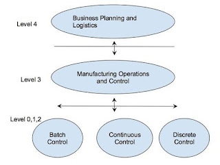
Level 0 defines the actual physical processes. 

Level 1 defines the activities involved in sensing and manipulating the physical processes. 

Level 2 defines the activities of monitoring and controlling the physical processes. These systems are typically implemented on PLCs and distributed control systems (DCSs). 

Level 3 activities are usually automated using MES, which also acts as the interface layer between the control layer (Level 2) and the enterprise resource planning (ERP) layer (Level 4).

Level 4 defines business-related activities that manage a manufacturing organization and is called Business Planning and Logistics. Level 4 activities are automated using ERP systems. 
Share |

Tuesday, August 22, 2017

Isomerization (Axens Process Licensing)


HIGH OCTANE C5/C6 CUTS VIA ISOMERIZATION PROCESSES

MEET MARKET DEMANDS WITH HIGH OCTANE ISOMERIZATION PROCESSES

From once-through to advanced recycle isomerization processes, we offer the complete line of isomerization solutions that, by increasing C5/C6 naphtha cut octane numbers up to 92, go far to meet tighter gasoline pool specifications. The isomerate product is free of sulfur, aromatics and olefins, making it an excellent gasoline pool component. Isomerization fits well with the trend to remove benzene precursors from reformer feedstock, and possible co-processing of light reformate fractions can resolve benzene content constraints. The question of which process to select will depend on a number of criteria such as feed composition and desired octane number. We have achieved a significant market penetration since the 90’s through the implementation of innovative process schemes combined with state-ofthe-art chlorinated alumina catalysts.

CHLORINATED ALUMINA CATALYSTS

Chlorinated alumina is the best catalyst to meet the need for today’s high octane requirements. Its high activity permits operation at the lower reactor temperatures that enable higher product RON and favor superior yields. The use of molecular sieve adsorbents on the feed and hydrogen make-up streams ensures the removal of feed contaminants and long catalyst lifetimes. Chlorinated alumina-based catalysts are also ideal for retrofitting idle units such as reformers or hydrotreaters with implementation of feed pretreatment and off-gas neutralization packages.  The substantial octane gain and reduced catalyst cost account for the short pay-back time, usually less than a year.

Our isomerization technologies employ ATIS-2L catalyst which provides an unsurpassed combination of high activity low cost and low platinum content.

ONCE-THROUGH C5/C6 ISOMERIZATION:  LOWEST INVESTMENT COST

This least-cost path to moderate octane gain can provide, in some cases, a sufficient boost to the gasoline pool octane. Typically, the octane for a feed having a C5 to C6 ratio of 40:60 will have an increase in RON from 70 to 83-84 after isomerization. We employ a permutable reactor design; that is, either reactor can be used in the lead or lag position or it can be operated independently during catalyst servicing. This assures ultra-high on-stream service.

OCTANE ENHANCEMENT WITH DEISOPENTANIZER (DIP) OR DEISOHEXANIZER (DIH)

The maximum octane number available from a oncethrough system is limited by the thermodynamic equilibrium of the C5/C6 mixture. Distillation is one way to achieve octane improvement by either allowing isomers to bypass the reactor (DIP) or by recycling normal paraffins to the reactor (DIH, shown hereafter). However, these approaches still leave normal paraffins in the product.


ADVANCED RECYCLE: IPSORB™

Ipsorb is the most economic path available to convert all normal paraffins to their iso-paraffins. A vapor phase mole sieve section is used to adsorb normal paraffins for recycle to the reactor.


ULTIMATE OCTANE: HEXORB™

The Hexorb process also completely adsorbs and converts all normal paraffins to isomers. The difference is that methyl pentanes (RON 74) are also converted, affording the highest possible octane for a C5-C6 feed (up to RON 92).

FOR BETTER BOTTOM LINE RESULTS

Our isomerization technologies are ready to help meet a refinery's octane objectives, whether it is for a new unit or debottlenecking and revamping of oncethrough and deisohexanizer units. Relative differences between the isomerization schemes with regard to investment cost, operating cost and product revenue, are shown in the table below. Our isomerization technologies are also well suited for stepwise installation of octane improvement projects. Typical payout times are on the order of a year.

COMMERCIAL EXPERIENCE

We entered the C5-C6 isomerization field late, in the 90’s, with a powerful R&D support at both lab and pilot scale sizes. Nevertheless, more than 50 isomerization units have been licensed by Axens, and since the marketing of ATIS-2L catalyst in 2003, more than 30 new units have been designed.

Share |

Cryogenic nitrogen plant

From Wikipedia, the free encyclopedia
Nitrogen, as an element of great technical importance, can be produced in a cryogenic nitrogen plant with a purity of more than 99.9999%. Air inside a distillation column is separated at cryogenic temperatures (about 100K/-173°C) to produce high purity nitrogen with 1ppm of impurities. The process is based on the air separation, which was invented by Dr. Carl von Linde in 1895.

Purpose
Gaseous Nitrogen (GAN) plant with production rate of 800 Nm3/hour
The main purpose of a cryogenic nitrogen plant is to provide a customer with high purity gaseous nitrogen (GAN). In addition liquid nitrogen (LIN) is produced simultaneously and is typically 10% of the gas production. High purity liquid nitrogen produced by cryogenic plants is stored in a local tank and used as a strategic reserve. This liquid can be vaporised to cover peaks in demand or for use when the nitrogen plant is offline. Typical cryogenic nitrogen plants range from 250 Nm3/hour to very large range plants with a daily capacity of 63.000 tonnes of nitrogen a day (as the Cantarell Field plant in Mexico).

Plant Modules
A cryogenic nitrogen plant comprises:
Warm End (W/E) Container
Compressor
·         Air receiver
·         Chiller (Heat exchanger)
·         Pre-filter
·         Air purification unit (APU)
Coldbox
·         Main heat exchanger
·         Distillation Column
·         Condenser
·         Expansion brake turbine
Storage and Backup System
·         Liquid nitrogen tank
·         Vapouriser

How the plant works

Flowsheet GAN Plant Linde Cryoplants Ltd.

Warm end process
Atmospheric air is roughly filtered and pressurised by a compressor, which provides the product pressure to deliver to the customer. The amount of air sucked in depends on the customer’s nitrogen demand.
The Air Receiver collects condensate and minimises pressure drop. The dry and compressed air leaves the air to refrigerant heat exchanger at about 10°C.
To clean the process air further, there are different stages of filtration. First of all, more condensate is removed, this removes some hydrocarbons.
The last unit process in the warm end container is the thermal swing adsorber (TSA). The Air purification unit cleans the compressed process air by removing any residual water vapour, carbon dioxide and hydrocarbons. It comprises two vessels, valves and exhaust to allow the changeover of vessels. While one of the TSA beds is on stream the second one is regenerated by the oxygen rich waste flow, which is vented through a silencer into the ambient environment.
Coldbox process
After leaving the air purification unit, the process air enters the main heat exchanger, where it is rapidly cooled down to -165°C. All residual impurities (e.g. CO2) freeze out, and the process air enters at the bottom of the distillation column partially liquefied.
Back up process
Liquid Nitrogen produced from the cold box transfers into the liquid storage tank. An ambient air vaporiser is used to vaporise stored liquid during peak demand. A pressure control panel senses the demand for gaseous nitrogen and regulates the gas flow into the end-users pipeline to maintain line pressure.
Applications for high purity nitrogen production
§  Ammonia production for the fertilizer industry
§  Float glass manufacture
§  Petrochemical
§  Purge gas
§  Blanketing/Inerting gas for tanks and reactor vessels
§  Amine gas treatment
§  Bearing seal gas
§  Polyester manufacture
§  Semiconductor manufacture
§  Photovoltaic manufacture
Share |

Monday, January 16, 2017

Pilot-Operated Relief Valve


Like other pressure relief valves (PRV), pilot operated relief valves (PORV) are used for emergency relief during overpressure events (e.g., a tank gets too hot and the expanding fluid increases the pressure to dangerous levels). The difference between PORV and conventional PRV is that pilot valves use system pressure to seal the valve. A PRV typically uses a spring to hold the disc or piston on seat. The essential parts of a PORV are a pilot valve (or control pilot), a main valve, a pitot tube, the dome, a disc or piston, and a seat. The volume above the piston is called the dome.

PORV are also called pilot-operated safety valve (POSV), pilot-operated pressure relief valve (POPRV), or pilot-operated safety relief valve (POSRV), depending on the manufacturer and the application. Technically POPRV is the most generic term, but PORV is often used generically (as in this article) even though it should refer to valves in liquid service.

Mode of functioning
The pressure is supplied from the upstream side (the system being protected) to the dome often by a small pilot tube. The downstream side is the pipe or open air where the PORV directs its exhaust. The outlet pipe is typically larger than the inlet. 2 in × 3 in (51 mm × 76 mm), 3 in × 4 in (76 mm × 102 mm), 4 in × 6 in (100 mm × 150 mm), 6 in × 8 in (150 mm × 200 mm), 8 in × 10 in (200 mm × 250 mm) are some common sizes.
The upstream pressure tries to push the piston open but it is opposed by that same pressure because the pressure is routed around to the dome above the piston. The area of the piston on which fluid force is acting is larger in the dome than it is on the upstream side; the result is a larger force on the dome side than the upstream side. This produces a net sealing force.
The pressure from the pilot tube to the dome is routed through the actual control pilot valve. There are many designs but the control pilot is essentially a conventional PRV with the special job of controlling pressure to the main valve dome. The pressure at which the control pilot relieves at is the functional set pressure of the PORV. When the pilot valve reaches set pressure it opens and releases the pressure from the dome. The piston is then free to open and the main valve exhausts the system fluid. The control pilot opens either to the main valve exhaust pipe or to atmosphere.

Snap acting
At set pressure the valve snaps to full lift, it can be quite violent on large pipes with significant pressure. The pressure has to drop below the set pressure in order for the piston to reseat (see blowdown in relief valve article).

Modulating
The pilot is designed to open gradually, so that less of the system fluid is lost during each relief event. The piston lifts in proportion to the overpressure. Blowdown is typically short.


Comparison to non piloted pressure relief valves
Advantages
  • Smaller package on the larger pipe sizes.
  • More options for control.   
  • Seals more tightly as the system pressure approaches but does not reach set pressure.
  • Control pilot can be mounted remotely.
  • Some designs allow for changes in orifice size within the main valve.
  • can be used in engines
Disadvantages
  • More complex, resulting in various fail-open failure modes.
  • More expensive at smaller sizes (starts to even out as pipe size increases).
  • Small parts in pilot valve are sensitive to contaminant particles.
Share |

Tuesday, October 4, 2016

Hydrogen - The Key Refinery Enabler

By. Stephen Harrison, Linde HiQ

In the 21st century, the term “scraping the bottom of the barrel” has become quite literal to the refining industry and hydrogen comes to the fore as a means to do just this

Download Complete Article
Only a few decades ago, the thick, heavy crudes being utilised today would not have even been a consideration for the production of mainstream products and were used mainly as bunker fuels. Thirty years ago crude quality was a good match with what was being demanded by the market, but today’s refiners are being compelled to dig deeply into the dregs of the remaining resources and must upgrade these crudes to reduce sulphur content and to keep up with market demand and environmental regulations. Hydrogen is therefore absolutely critical to convert this poor quality crude oil into modern-day products, and to comply with strict environmental mandates.

Although these heavy crudes are actually cheaper, refineries are faced with the additional expense of upgrading to sophisticated processes to refine them to the required standards and product slate meeting demand. The alternative is to pay a premium for the lighter crudes. This awkward choice has already impacted many refineries, notably on the east coast of the US , where refineries originally built to process light and sweet crudes have had to shut down because they could not fund the technology upgrade necessary to process heavier crudes. The cost of hydrogen is part of the premium that the refiners must pay to process cheaper crudes economically.

The challenge is made more complex by the fact that no two refineries are alike and that the naturally occurring hydrocarbon distribution in crude does not always match customer demand. Various additional processing steps are required to re-adjust the molecules, reshape them and remove contaminants to ensure the refinery products meets the requirements for end-use and the product demand profile, as well as environmental performance.

Hydrogen is a key enabler allowing refineries to comply with the latest product specifications and environmental requirements for fuel production being mandated by market and governments and helping to reduce the carbon footprint of their plants.

Margins are tight in the highly competitive refinery business, a situation exacerbated by the costs of creating low sulphur fuels from heavier, more sour crude, as the world’s crude oil resources dwindle. The sulphur content of the world’s diminishing crude oil resources is higher than ever before as oil companies are forced to tap into a cheaper but lower quality of crude that requires more refining to meet tightening environmental standards and while maximising margins. Product sulphur levels are lower than ever before — for instance, 30 parts per million (ppm) in gasoline and 15 ppm in diesel fuels.

Growth in demand
From a global perspective hydrogen is demonstrating significant growth. Large heavy crude oil reserves, still under development, may increase the hydrogen demand ever further. Two examples are the extra heavy crude oil in the Orinoco Belt in southern of Venezuela and the Canadian Oil Sands. While there are many refinery configurations, all refineries harness large quantities of hydrogen across a spectrum of operations. Hydrogen is utilised in several refining processes, all aiming at obtaining better product qualities. The main processes include hydrotreating of various refinery streams and hydrocracking of heavy products.

While the lighter, sweet crudes require less processing, the heavier, sour crudes contain higher levels of sulphur, other contaminants and fractions. Processing them typically begins with the same distillation process as for the sweet crudes to produce intermediate products, but additional steps are necessary.

Hydrotreating is one such process, introduced to remove sulphur, a downstream pollutant, and other undesirable compounds, such as unsaturated hydrocarbons and nitrogen from the process stream. Hydrogen is added to the hydrocarbon stream over a bed of catalyst that contains molybdenum with nickel or cobalt at intermediate temperature, pressure and other operating conditions. This process causes sulphur compounds to react with hydrogen to form hydrogen sulphide, while nitrogen compounds form ammonia. Aromatics and olefins are saturated by the hydrogen and lighter products are created. The final product of the hydrotreating process is typically the original feedstock free of sulphur and other contaminants. Single or multiple product streams (fractionated) are possible, depending on the process configuration.

The hydrocracking process is a much more severe operation to produce lighter molecules with higher value for diesel, aviation and petrol fuel. Heavy gas oils, heavy residues or similar boiling-range heavy distillates react with hydrogen in the presence of a catalyst at high temperature and pressure. The heavy feedstocks are converted (cracked) into light distillates — for example, naphtha, kerosene and diesel — or base stocks for lubricants. The hydrocracker unit is the top hydrogen consumer in the refinery. Hydrogen is the key enabler of the hydrocracking to reduce the product boiling range appreciably by converting the majority of the feed to lower-boiling products. Hydrogen also enables hydrotreating reactions in the hydrocracking process; the final fractionated products are free of sulphur and other contaminants. Other refinery processes including isomerisation, alkylation and tail gas treatment also consume small amounts of hydrogen.

Critical decision
Considering that the cost of a refinery expansion can be in the order of US$1billion, with hydrogen supply representing in some cases about 10% of this investment, the decision concerning the optimum way to source this hydrogen has become a critical one. In many cases, refinery operators see the investment into hydrogen supply as a defensive outlay necessary to remain competitive in the market.

Hydrogen is required in large volumes – typically 10-200 000 Nm3/hr on a refinery, but is needed for a variety of applications in several different scales of supply. Due to hydrogen representing a significant percentage of a refinery’s total investment, a pivotal decision confronting operators is the supply method. There are essentially three options for large scale hydrogen supply.

Firstly, the refiner can build an on-site hydrogen production plant, which it owns and operates using its own personnel. An advantage of this option is that hydrogen production becomes fully integrated with the other refinery processes. While this enables the refinery to keep control of its own hydrogen supply, this option requires more capital and demands skilled attention from the refinery labour force for efficient operation, maintenance and repair. If the in-house team is unable to operate the plant efficiently, the refinery will incur financial losses, including increased consumption of natural gas and even other more costly raw materials such as naphtha, water and power. Loss of hydrotreated products attributed to poor reliability may also be a concern.
Share |

Share

Twitter Delicious Facebook Digg Stumbleupon Favorites